
Introduction
In CNC milling, engineers and designers face the pivotal question of whether to use counter sink holes or counter bore holes to assemble their designs. A small misunderstanding might cause the tops of the screws to stick out, interfere with the assembly, generate points of focused stress, or may, in the worst cases, cause the designs to fail. The problem starts with a general unawareness of the nuances between the two kinds of holes. Current approaches to this problem use experience instead of Design for Manufacturability.
In this article, a structured way to make a difference by following authoritative documents, such as ASME Y14.5, will help engineers with designs to systematically determine the right path to pursue according to function, materials, or costs. We will start our journey to optimize designs by exploring the seven aspects of design.
What Are the Fundamental Functional Differences Between Countersink and Counterbore?
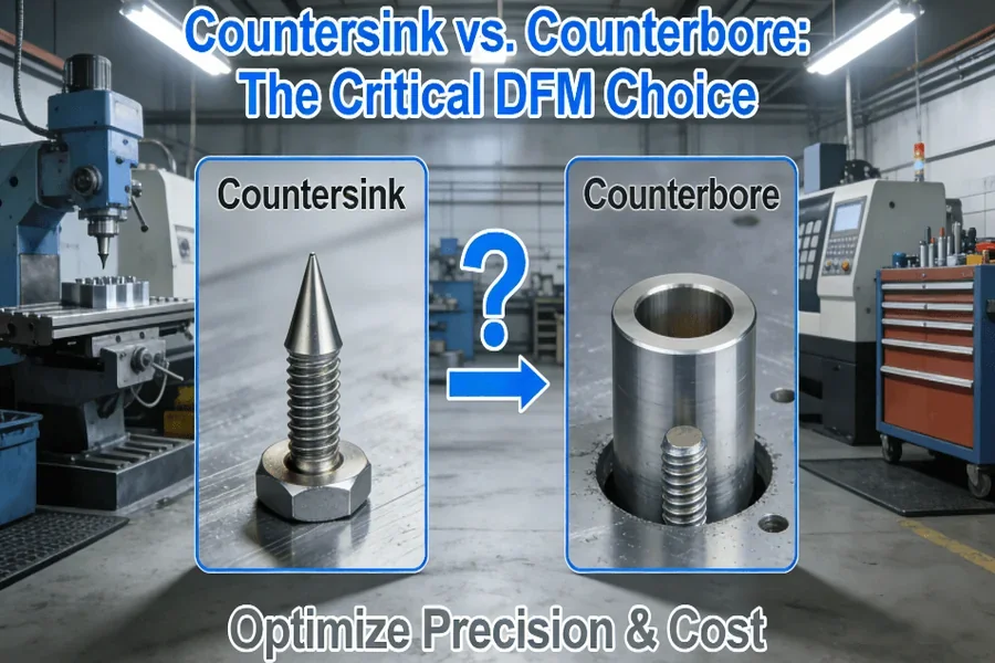
Countersink and counterbore holes are different in their use during assembly. A hole with a counter sink contains a cone-shaped hole that accepts a flat-headed screw. This enables a finish on the top to be achieved. Secondly, a hole with a counterbore contains a cylindrical hole with a flat bottom. This is used to hide a socket cap screw.
Geometric Shape and Structural Definitions
A countersink hole has a conical shape to receive flat head screws, creating a flush finish. By contrast, there is a counterbore hole that is cylindrical and has a flat bottom to receive socket head cap screws. This difference is reflected in their usage. Since countersinks are used for aesthetics and airflow, geometric considerations come to the forefront. Likewise, for counterbores, usage is driven by strength and hiding. It is important to quote the ASME Y14.5-2018 specification, as it is important to have clear geometric definition.
2. Standard Fastener Types and Compatibility
Countersinks are designed to be used with flat-head screws of the same angle as the hole, such as 82° or 90°, fitting perfectly. However, counterbores are used together with socket head cap screws that need exactly the same diameter and depth of the hole so that the fastener head can be contained. This is usually the way compatibility controls the method of assembly: Countersinks will be suited to applications where a flush surface is all-important-for example, consumer electronics-while counterbores are ideal for structural joints in machinery where load distribution is the main issue at stake.
3. Visualization and Reference to Authority Standards
The ambiguity should be avoided, and engineering drawings must be provided with elaborate schematics of the hole profiles. The application of standards such as ASME Y14.5 assures uniformity in interpretation by teams. For example, the symbols for concentricity and depth tolerances in the standard help in ensuring proper alignment between the pilot and main holes, thereby reducing errors in complex assemblies.
How Does Your Choice Directly Impact Part Strength and Structural Integrity?
The choice of countersink or counterbore screw holes has a large influence on mechanical properties. A countersink cutaway will remove more material closer to the surface, creating a potential spot for a stress concentration when loaded dynamically. A counterbore load distribution alleviates this issue by increasing the screw head’s tensile strength.
- Performance with Various Kinds of Loads: In shear, counterbores can be considered superior to countersinks because of material distribution, thereby creating fewer points of potential stress risers. While counterbores can be undesirable in thin areas because of the conical removal of material, thereby creating potential points of weakness near the surface, countersinks can cause deformation should they not closely align with the screw angle. In tension, counterbores can offer superior clamping with an equal distribution of pressure provided by the flat seat.
- Stress Concentration Analysis: Finite Element Analysis (FEA) studies show that stresses have a higher concentration factor in countersinks and can lead to a brittle fracture for materials such as cast iron. The effect of a gradual transition is to lower stresses up to 30% in components prone to fatigue. This means that counterbores are preferable for high-cycle use in aerospace brackets and automobile components.
- Influence of Material Properties: For a material like aluminum, countersink techniques can be useful if properly managed for depth, but for a hard polymer or composite material that is more brittle, the taper on a countersink may produce cracking. Counterbores would be more reliable for such materials because more material integrity would be maintained. Material hardness, such as with hard alloys, may necessitate specialized countersink tooling.
What are the key DFM considerations for machining each hole type accurately?
In order to get accuracy in hole machining, it requires consideration of tool choice and parameter optimization. In countersink holes, it requires angle tools to prevent over-cutting. In counterbores, it requires multi-step drilling operations.
1. Optimizing Parameters for Countersink Machining
To create a perfect countersinking, one needs sharp tools, which involve optimal cutting conditions. Fast spindle speeds with slow feeds avoid chatter when working with aluminum, while Peck Drilling cycles remove chips efficiently. Accuracy is paramount, as any error of up to 0.1mm in depth can lead to screw protrusion. On-machine probes aid in real-time verification, ensuring accuracy, with more than 20% reduced scrap rates.
2. Tool Selection and Process Planning for Counterbore
The process of counterboring needs rigid end mills or counterbore tools. The process becomes more accurate with multi-step processes such as pilot drilling and counterboring. Computer-Aided Manufacturing toolpaths can be optimized for less tool deflection when creating high holes. In high-volume production, custom fixtures can be highly helpful. Additionally, single-set-up 5-axis CNC machining can be cost-free per part.

3. Importance of In-Process Measurement and Control
By applying statistical process control (SPC), variations in the crucial parameters such as diameter and depth are identified. Gauging systems incorporated with CNC machines help control variations due to tool wear on machined holes and maintain a tolerance of ±0.05mm. Such a pro-active system complies with the requirements of ISO 9001 standards and provides holes with the design specifications without reworking.
How to Select the Optimal Hole Type Based on Material and Application Scenarios?
A systematic process must consider functional requirements, material performance, and economics. The use of countersinks has priority in the aerospace industry, where aeronautic panels are concerned, whereas the use of counterbores has priority in the equipment industry.
1. Decision Flowchart for Different Industries
A systematic flowchart can be used to make this selection easier. It is necessary to begin by evaluating functional requirements such as whether the surface needs to be flushed or whether it must have high strength. When considering aerospace parts, for example, as aerodynamics come into play, countersinks are used. However, for heavy machinery, counterbores are used because dynamic loads can be better supported.
2. Case Studies from Aerospace, Medical, and Automotive Industry Sectors
In a design of a drone arm, changing from counterbore to countersink resulted in a 15% reduction in weight without affecting its integrity. In a medical implant design, counterbores were necessary to handle the process of sterilization. In complex problem settings, it is helpful to Consult authoritative sources such as the Countersink vs Counterbore resource to weigh various considerations.
3. Natural Integration of Reference Links
When dealing with complex designs, engineers have the benefit of using specialized knowledge. For instance, the article Countersink vs Counterbore contains some guidelines that help avoid errors when dealing with specific materials. This article is used in conjunction with the principles of DFM.
Why Do Certified Quality Management Systems Matter for Precision Hole Machining?
The ISO 9001:2015 and AS9100D certifications not only indicate the element of compliance but the essence of ‘Culture of Continuous Improvement’. The above-mentioned standards demand traceability right from design to delivery. This becomes very essential in the aerospace and medical industry sectors.
- Consistency Throughout Design, Production, and Testing: Certifications such as ISO 9001:2015 ensure a strict process from the design review stage to the inspection stage. This way, it is guaranteed that every hole created adheres to specifications. This is particularly significant given that, in the manufacture of health equipment, for instance, any form of defect can be calamitous. A certified standard, for instance, would ensure regular checks on the specifications of drilling.
- Application of FAI and SPC in Hole Machining: First Article Inspection (FAI) verifies hole sizes versus the CAD model before production, while SPC charts show long-term data. The precision machining approach improves the defect rate by up to 25% through data-driven analysis. Organizations following the approach, and therefore companies with an AS9100D rating, show traceability and a willingness to improve.
- Brand Mentions and Quality Assurance: However, with a strong quality management system in place, such risks are reduced as checks are carried out at various levels. Thus, complicated hole features are made with preciseness while maintaining efficiency.
Can You Achieve Both High Quality and Cost-Effectiveness? A Case Study Insight
A company reworked the placement of turbine blade holes from the counter-sunk to the counterbored type, resulting in a 30% reduction in stress concentration points and a 20% reduction in assembly time. Using the principles of DFM, the company enhanced the reliability of the components at the same cost per unit.
1. Case Example: Optimization of an Aerospace Bracket
A satellite bracket design utilized counterbores, but DFM analyses showed that using countersinks could decrease weight by 12% and machining time by 20% with no compromise on strength. Optimizing tool paths with 5-axis CNC machining enabled a cost reduction of up to 30%, which adheres to standards AS9100. This scenario emphasizes that ideas on material choice and advanced machining techniques work well when combined.
2. Cost-Benefit Analysis
By measuring the cost of the tooling against the lifetime savings, the initial spend of the counterbores is higher due to the complex fixtureing system needed. Yet the single setup capability of machining equally nullifies the disparities. Taking an holistic approach towards the decision results in the balance of the unit cost with the overall reliability.
3. Natural Integration of Service Links
These optimisations, which are a result of DFM, are at the heart of expert CNC milling services. To discover more about these services means to find solutions to difficult problems with optimum results in terms of quality, cost, and production.
Conclusion
Where to employ countersink holes versus counterbore holes is not easy to determine. In order to evaluate this decision properly, engineers must look towards proper DFM principles. In doing so, they can mitigate potential issues that may arise. Engineers must remember that it is not a simple decision but rather one that influences many areas. Engineers must rely on a data-driven decision to turn a potential problem into a key success area.
FAQs
Q: What is the standard angle on a typical countersink?
A: The usual for imperial screws is 82°, whereas in metric screws the angle is 90°. High accuracy in matching angles is very important to avoid incorrect seating and to obtain flush fits, especially where critical applications in certain industries like aerospace make use of 100° or 120° angles.
Q: It is best not to countersink the hole before machining it. Otherwise, there is
A: Provide sharp tooling and then utilize proper cutting conditions — higher speeds and lower feeds, which prevent burrs from forming. Peck drilling or back deburring tools can be used to remove the burrs, reducing the imperfections and providing a clean finish which is critical for high tolerance assemblies.
Q: In which applications is a counterbore absolutely necessary?
A: A counterbore is necessary in structural members subjected to pronounced tension, like machine frames, where it is necessary to conceal screws. It is superior to a countersink in terms of distributing the load.
Q: How does material selection impact the choice between countersink and counterbore?
A: Brittle materials such as cast metals make use of counterbores instead, as they help avoid fracturing, whereas thin sheets might need countersinks to achieve lightness. Hard materials will increase the difficulty of machining, making counterbores the preferable choice.
Q: What tolerances must be specified for a counterbore?
A: Emphasis is on diameter, depth, and concentricity relative to the pilot hole. It is recommended in GD&T to control these characteristics with respect to datums to provide the correct alignment to screws and to prevent assembly problems, usually tolerancing depth to ±0.1mm.
Author Bio
The author is also a specialist in precision manufacturing, with expertise in CNC machining solutions. At LS Manufacturing, engineers can trust them for assistance in dealing with challenging parts. They have expertise in providing high-precision services that are certified in ISO 9001 and AS9100D. To take your ideas to the next step and make something out of them, visit they for a free DFM analysis.